Page 723 - Yamawa_European_Catalogue_YEU21
P. 723

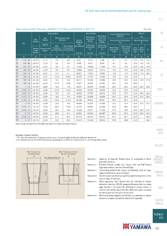
24. Drill size and recommended hole size for cutting taps


                                                                                                                  Intro


            Taper Internal Pipe Threads - Rc(BSPT)-PT (refer to JIS B 0203 or ISO 7-1)                 Unit: mm

                                   Thread Standards           Minor Diameter   Recommended Bored Hole Sizes   Reference  SP
                                                                       When Threads  (reference)
                                                              When Threads                           Tap
                                Basic   Eff ective Thread Length       do not have
                         Basic   Diameter   (Minimum)  Pipe End  have non-Full   the non-Full   Maximum Size of Straight Bored   Basic Diameter Position.
                        Diameter                       (Workpiece   Threads  Threads  Hole           ℓg
                 Size
                               Pipe End                 Face)
                                        When   When Threads  (Basic Diamater)  Position away   Position away   When Threads  SL
                        Tolerance  Tolerance in axial   Threads have   do not have the   from Pipe End   from Pipe End   When Threads   do not have   Long   Short
                                                                by ℓ
                                                                         by t
                         in radial   direction  non-Full Threads non-Full Threads  have non-Full   the non-Full   Thread  Thread   Rc
                         direction  c    ℓ        t                              Threads  Threads  Type  Type
                                                       Basic Size  Basic Size  Basic Size
                 1        2      3       4       5       6       7       8        9       0      !   "    £
             PT  1/16 - 28  ±0.071  ±1.13  6.2   4.4    6.561   6.174   6.286    6.1      6.2   13.0  10.5  10.1
                                                                                                                   PO
             PT   1/8 - 28  ±0.071  ±1.13  6.2   4.4    8.566   8.179   8.291    8.1      8.2   13.0  10.5  10.1
             PT   1/4 - 19  ±0.104  ±1.67  9.4   6.7   11.445  10.858   11.026   10.7     10.9  21.0  12.5  15.0
             PT   3/8 - 19  ±0.104  ±1.67  9.7   7.0   14.950  14.344   14.513   14.2     14.4  21.0  14.0  15.4
             PT   1/2 - 14  ±0.142  ±2.27  12.7  9.1   18.631  17.837   18.062   17.6     17.9  25.0  17.0  20.5
                                                                                                                   ST
             PT   5/8 - 14  ±0.142  ±2.27  (13.4)  (9.65)  20.587  19.750  19.984  19.6   19.8  25.0  -   -
             PT   3/4 - 14  ±0.142  ±2.27  14.1  10.2  24.117  23.236   23.480   23.0     23.3  25.0  19.0  21.8
             PT   7/8 - 14  ±0.142  ±2.27  (15.2)  (10.9)  27.877  26.930  27.196  26.7   27.0  28.0  -   -
             PT    1 - 11  ±0.181  ±2.89  16.2   11.6  30.291  29.279   29.566   29.0     29.3  32.0  22.0  26.0
                                                                                                                 ROLL
             PT  1  1/8 - 11  ±0.181  ±2.89  (17.4)  (12.5)  34.939   33.855   34.158   33.6  33.9  32.0   -  -
             PT  1  1/4 - 11  ±0.181  ±2.89  18.5  13.4  38.952   37.796   38.115   37.6  37.9  32.0   24.5  28.3
             PT  1  1/2 - 11  ±0.181  ±2.89  18.5  13.4  44.845   43.689   44.008   43.5  43.8  32.0   25.5  28.3
             PT  1  3/4 - 11  ±0.181  ±2.89  (18.5)  (13.4)  50.788   49.632   49.951   49.4  49.7  32.0   -  -
             PT    2 - 11  ±0.181  ±2.89  22.8   16.9  56.656  55.231   55.600   55.0     55.4  35.0  27.5  32.7  CARBIDE
             PT  2  1/4 - 11  ±0.216  ±3.46  (26.7)  (18.6)  65.710   64.041   64.548   63.8  64.3  50.0   -  -
             PT  2  1/2 - 11  ±0.216  ±3.46  26.7  18.6  72.226   70.557   71.064   70.3  70.8  50.0   32.0   37.1
             PT    3 - 11  ±0.216  ±3.46  29.8   21.1  84.926  83.064   83.607   82.8     83.3  52.0  36.0  40.2
             PT  3  1/2 - 11  ±0.216  ±3.46  31.4  22.4  97.372   95.410   95.972   95.1  95.7  52.0   -  46.2   LONG
             PT    4 - 11  ±0.216  ±3.46  35.8   25.9  110.072  107.835  108.453  107.6  108.2  55.0  -  46.2
            Note: Length toward End of Smaller Diameter from Basic Diameter Position
                                                                                                                 HAND
                                                                                                                 TAPS
            REMARKS DURING TAPPING
            1. PT internal threads have R design on their crests. The tap should cut threads with their thread rot.
            2. On thread drawing non-full threads. If you are going to cut effective thread length ℓ., use the tap of long type.
                                                                                                               EG (STI)


                    When Threads have      When Threads do not have
                     non-Full Threads        the non-Full Threads
                                                                                                               SPECIAL
                                 Basic Diameter Position
                                                               Remarks 1.   Opening of Internal  Thread (Face of workpiece) is Basic   THREADS,
                                                                        Diameter Position.                     GAUGES
                                                               Remarks 2.   Effective Thread Length has 2 types: with non-Full Thread
                                                                        Type and without non-Full Thread Type.
                                                               Remarks 3.   Concerning bored hole shape, considering load on taps,
                                                                        taper bored hole is recommended.       THREAD
                                                               Remarks 4.   Use the machines that has synchronized feed system in the   MILLS
                                                                        case of taper bored hole.
                                                               Remarks 5.   When applying taper bored hole, by referring to values
                                                                        shown in columns 258, prepare the taper hole by using
                                                                        pipe reamer (1/16 taper). By referring to values shown in   DIES
                                                                        columns 9 and 0, select the drill diameter before reaming
                                                                        by taking reamer’s margin into account.
                                                               Remarks 6.   When preparing straight bored hole, by referring to values
                                                                        shown in columns 9 and 0, select drill diameter.
                                                                                                               CENTER
                                                                                                                DRILLS


                                                                                                               Technical
                                                                                                                  info


                                                                                                                721
   718   719   720   721   722   723   724   725   726   727   728