


Page 642 - Yamawa_European_Catalogue_YEU21
P. 642
5. Tapping Torque

    Intro


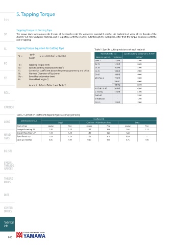
            Tapping Torque of Cutting Taps
    SP      The torque starts increasing as the threads of thechamfer enter the workpiece material. It reaches the highest level when all the threads of the
            chamfer cut into workpiece material, and is in plateau until the chamfer cuts through the workpiece. After that, the torque decreases until the
            end of tapping.

    SL      Tapping Torque Equation for Cutting Taps              Table 1  Specifi c cutting resistance of each material

                                                                      Materials to be cut  Specifi c cutting resistance kc N/mm 2
                      tanθ
              Tc =          . x kc × K(D-Do)² × (D+2Do)                                            2
                     24000                                         Material symbols  Hardeness  N/mm

                                                                  5t44-2        133HB           3700
    PO
              Tc :   Tapping Torque (Nm)                          Ck 15         141HB           3600
              kc :   Specifi c cutting resistance (N/mm ) 2       Ck 35         162HB           3700
              K :    Correction coeffi  cient depending on tap geometry and chips  Ck 45  188HB  3900
              D :    Nominal Diameter of Tap (mm)
                                                                  Ck 60         188HB           4000
              Do :   Bored hole diameter (mm)
    ST                                                            42 CrMo 4     193HB           3600
              θ :    Thread half angle (°)
                                                                                30HRC           4900
                     kc and K : Refer to Table 1 and Table 2                    40HRC           5500
                                                                  X 6 CrNi 18 10  209HB         4200
    ROLL                                                          C 105 W2      175HB           5300
                                                                  CnZn40         -              2300
                                                                  G-AISi8Cu3     -              1300
                                                                  GG-25         193HB           2900
    CARBIDE

            Table 2  Correction coeffi  cient depending on each tap geometry
                                                                 Coeffi  cient K
    LONG       Materials to be cut       Steel               Cast iron + Alluminium alloys    Brass
             Kinds of tap         coarse        fi ne        coarse        fi ne       coarse        fi ne
             Straight fl uted tap 5P  1.35      1.15         1.25         1.08          1.60         1.12
             Straight fl uted  tap 1.5P  1.43   1.50         1.30         1.25          1.68          -
    HAND     Spiral fl uted tap    1.15         1.25         1.05         1.10          0.85          -
    TAPS
             Spiral pointed tap    0.95         1.00         0.80         1.00          0.75         1.00


    EG (STI)


    SPECIAL
    THREADS,
    GAUGES


    THREAD
    MILLS


    DIES


    CENTER
    DRILLS


    Technical
    info


       640

